San Francisco – Oakland Bay Bridge – Featured Archive
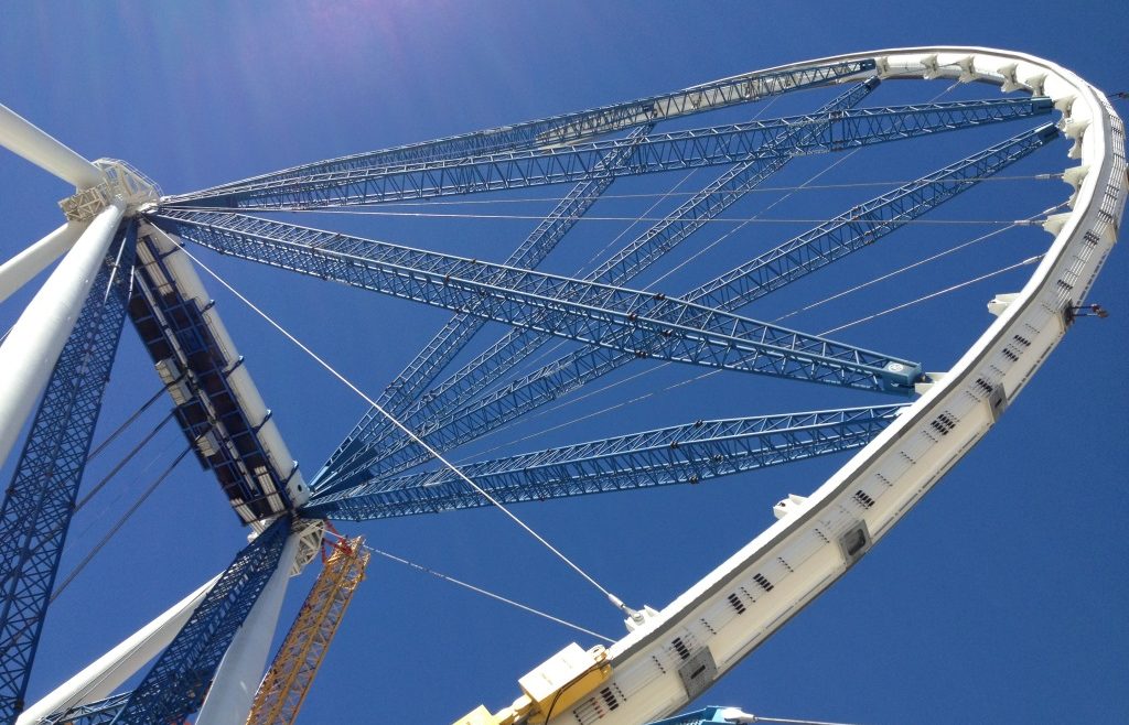
San Francisco – Oakland Bay Bridge – Featured Archive https://www.southlandholdings.com/wp-content/uploads/home_slide1-1024x682.jpeg 1024 682 Southland Holdings https://www.southlandholdings.com/wp-content/uploads/home_slide1-1024x682.jpegThe San Francisco/Oakland Bay Bridge is not only a critical piece of infrastructure, but a marvel of modern engineering. The work involved in constructing the iconic self-anchored suspension span of this bridge included the use of innovative techniques that pushed the boundaries of modern construction. In this post, we’ll dive into some of the most fascinating aspects of the project, including cable band installation, suspender rope installation, and load transfer works that were essential during construction.
Cable Band Erection
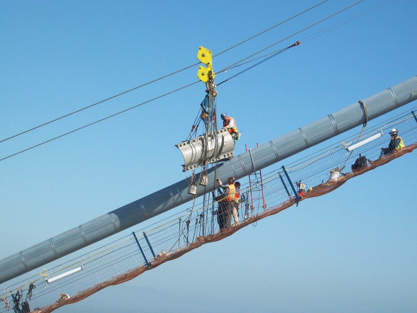
Following installation of the PWS (Prefabricated parallel Wire Strands) that made up the main cable, and compaction of those 137 strands, attention turned to cable band erection. There were a total of 114 cable bands, each unique due to varying slope and rotation of the main cable. The cable bands were composed of two halves that were fastened together with 2” diameter bolts and tensioned to a predetermined load.
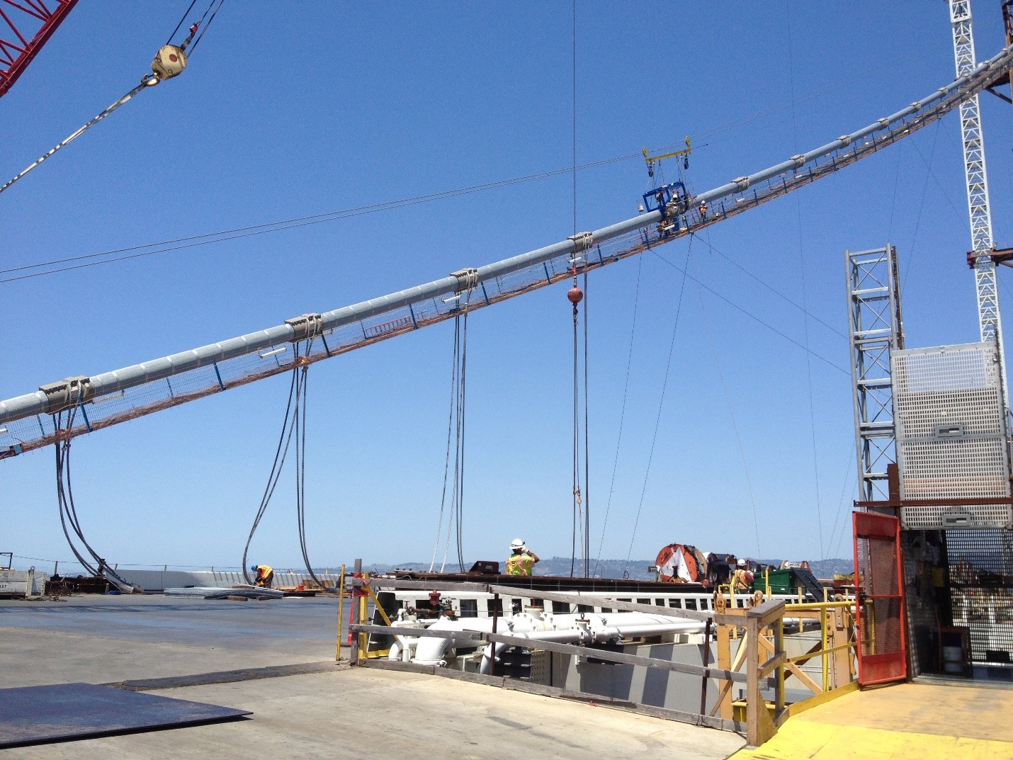
Suspender Rope Erection
Of the 114 cable bands, 100 had a pair suspender ropes. Various methods were used to erect the suspenders, depending on the height above the deck. For locations that a crane could not reach, a custom designed frame was fabricated that allowed a winch to pull the suspender into position. The center of each suspender rope was marked during fabrication to verify suspender was properly placed during installation.
Load Transfer
Suspender Rope Jacking
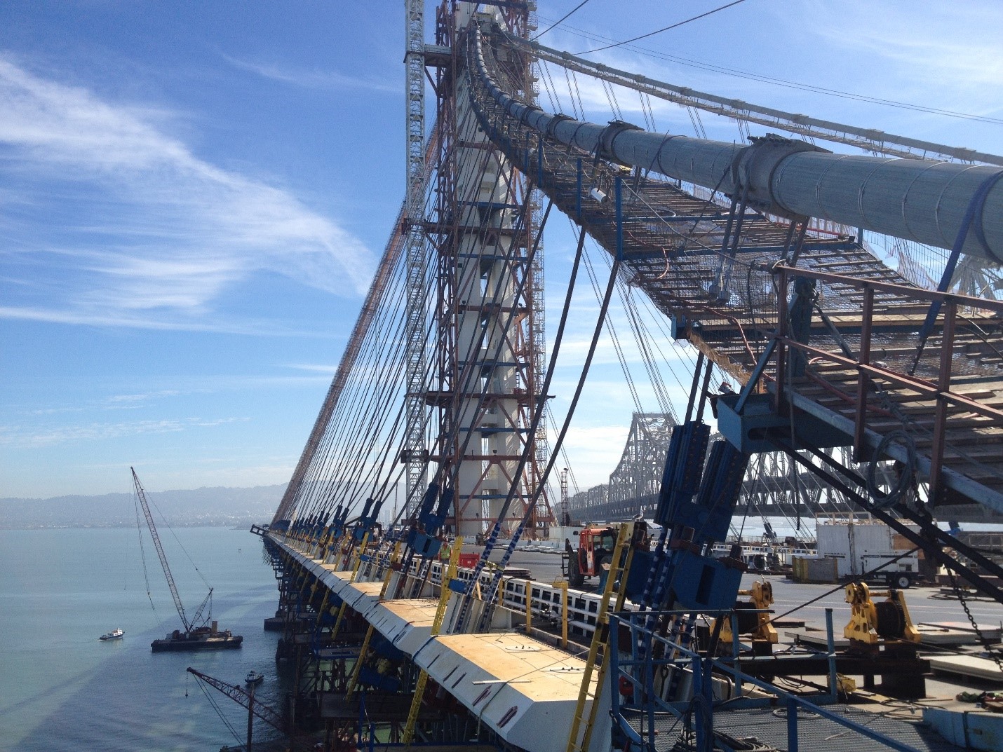
The load transfer operation was a critical phase during the Bay Bridge’s construction. During this operation the permanent suspender ropes were sequentially tensioned to transfer the weight of the bridge deck from the temporary truss to the main cable. To perform this operation, engineers utilized a jacking system consisting of friction clamp weldments, threaded rods, and jacking beams at each suspender location to connect the suspenders to the bridge superstructure.
The friction clamp weldment was comprised of thick steel plates with machined surfaces secured to each suspender rope using eighteen 1.25” diameter A490 bolts. The friction clamps were connected to a lower jacking beam using 4 high-strength all-thread rods. The jacking beams were equipped with two hydraulic jacks. Each individual system was capable of supporting the maximum load transfer design load of 800 tons, lifting the bridge superstructure, and permanently connecting the suspender to the bridge superstructure.
These jacking systems were vital to equalize the loads during jacking operations, ensuring the structural integrity of the suspender ropes. The precision required in this process was remarkable, as each jacking location needed to lift and transfer the load incrementally to avoid putting excess strain on the structure during the load transfer operation.
Jacking Saddle & Tower Adjustments
A unique aspect of the SAS span was it’s continuous main cable; each end of the cable was anchored into the deck at the east end and wrapped around the west pier. This imposed challenges as the main cable was loaded during load transfer. Prior to cable erection, the permanent tower was “pulled” approximately 20” west. To perform this operation, ten 2.25” strands were connected between the top of the tower to the adjacent island. Jacks on the lower end of the strands were used to manipulate the movement of the tower. During load transfer, the jacks were adjusted to allow the tower to move at predetermined increments in order to balance the horizontal reactions from the cable.
Additionally, the cable between the two west deviation saddles needed to be adjusted during load transfer to maintain equal tension with the side span cable. The jacking saddle, positioned between the two deviation saddles, was used to perform this operation. At each of the jacking saddle’s four legs, four 300T jacks were used to adjust the location of the jacking saddle. Throughout load transfer, the jacking saddle was sequentially “pushed” a distance of approximately 5’-5”.
In total, the team managed to jack and transfer the load in multiple stages, demonstrating incredible precision and control in their engineering methods. It’s a testament to the planning and expertise involved in constructing a bridge of this magnitude.
The Unsung Heroes of Bridge Engineering
The construction of the San Francisco/Oakland Bay Bridge is a testament to the power of modern engineering. Each phase of the project required careful planning, precision execution, and immense technical expertise. These complex processes were integral in ensuring that the bridge could handle the immense loads placed upon it, while also standing as a symbol of engineering excellence for generations to come.
The next time you drive across the Bay Bridge, remember the countless hours of engineering and ultimately the successful load transfer process, that made this marvel of modern construction possible.
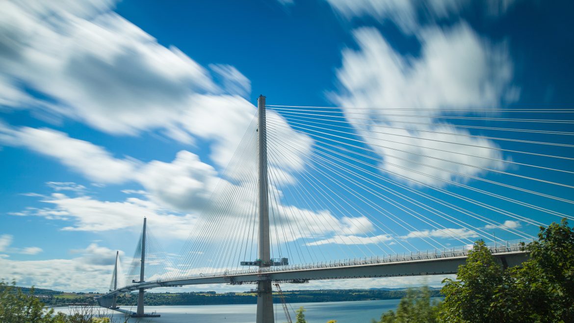
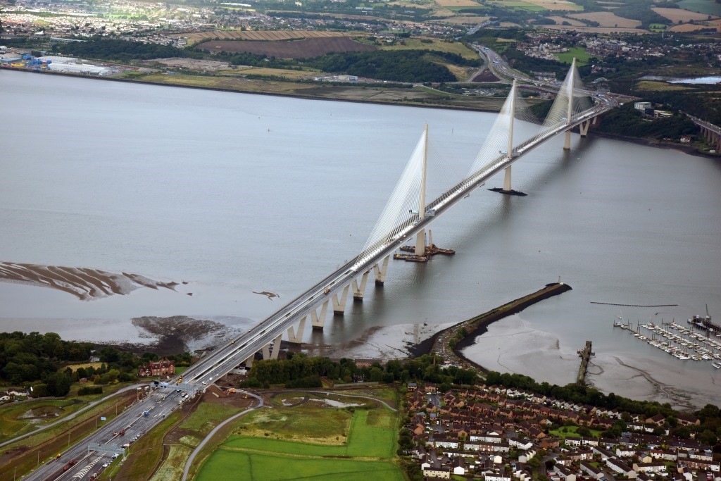
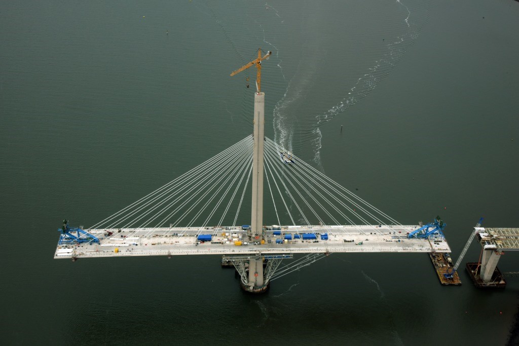
 Rising high above the Firth of Forth, the three towers of the Queensferry Crossing are perhaps the most striking feature of the bridge. These towers, each reaching heights from 207-210 meters, were designed to anchor the cables that support the bridge deck. The reinforced towers start at bedrock nearly 40 meters below the water.